


Views: 0 Author: Site Editor Publish Time: 2026-10-25 Origin: Site


Industrial exhaust systems operate under constant stress in highly corrosive or moisture-dense environments. Chemical vapors, extreme humidity, and continuous vibration degrade standard materials rapidly. When standard metals fail, facilities face severe safety risks and operational downtime. Improper specification of fan enclosures leads to catastrophic flange failures, severe vibration transmission, and costly maintenance bottlenecks when technicians cannot easily access internal components. Mitigating these risks requires a rigorous approach to specifying the enclosure system. Engineers must focus heavily on mounting flange design, precise clearance tolerances, and engineered service access points. A well-designed composite enclosure ensures long-term reliability. It protects internal rotating assemblies while providing safe, efficient access for maintenance personnel. Understanding the exact mechanical requirements for these enclosures prevents premature equipment failure and keeps industrial ventilation systems running efficiently.
Flange Integrity is Paramount: Proper load distribution and vibration isolation at the mounting flange prevent stress fractures in composite materials.
Clearance Dictates Performance: Strict adherence to internal blade-to-housing and external structural clearances prevents aerodynamic stalling and mechanical interference.
Serviceability Reduces Downtime: Integrating removable duct sections and accessible fiberglass covers transforms multi-hour maintenance tasks into rapid service intervals.
Manufacturing Method Matters: Specifying housings produced via fiberglass compression molding ensures tighter dimensional tolerances and superior structural consistency compared to traditional hand lay-up methods.
Defining the operational baseline for industrial exhaust and axial flow fans requires a deep understanding of the installation environment. Harsh settings like wastewater treatment plants, chemical processing facilities, and pulp mills destroy standard equipment. Airborne corrosives attack exposed metals continuously. High humidity accelerates oxidation, while chemical fumes break down standard industrial coatings. In these settings, the primary enclosure acts as an impenetrable barrier. It must support the dynamic weight of the rotating assembly while resisting chemical degradation from the inside out. The success criteria for these enclosures include absolute structural stability, zero chemical degradation over decades of use, and seamless physical integration with existing ductwork.
Fiberglass reinforced plastic (FRP) offers distinct mechanical advantages over carbon steel and aluminum. The most significant benefit is its inherent corrosion resistance. Unlike metals that require constant recoating, galvanization, or specialized epoxy paints, FRP resists chemical attack throughout its entire matrix. When engineers specify premium vinyl ester resins, the composite material withstands continuous exposure to harsh compounds like hydrogen sulfide, sulfuric acid, and sodium hypochlorite. This resistance applies equally to highly acidic and highly alkaline environments, making it a versatile choice for mixed-chemical exhaust streams.
FRP boasts an exceptional strength-to-weight ratio. It provides the tensile strength necessary to support heavy industrial impellers, motors, and drive assemblies, but weighs roughly 30% as much as carbon steel equivalents. This weight reduction simplifies the installation process. It reduces the dead load on building roof structures, mounting skids, and suspended ceiling supports. Over the lifecycle of the equipment, these material properties drastically reduce maintenance requirements. Facilities eliminate the need for routine rust removal, repainting, and structural patching. The extended lifecycle of composite materials directly translates to sustained operational efficiency and fewer unexpected shutdowns for structural repairs.
The reliability of a composite enclosure depends entirely on how the manufacturer produces it. Traditional open-mold hand lay-up processes rely heavily on operator skill. Workers manually apply layers of fiberglass mat and liquid resin onto a mold, rolling out air bubbles by hand. This method often results in inconsistent wall thicknesses, trapped air voids, and variable resin distribution. For critical industrial applications, these inconsistencies create weak points. High-stress areas, particularly around mounting points and structural flanges, require absolute uniformity to prevent failure under dynamic loads.
Advanced manufacturing techniques solve these structural issues entirely. Specifying components produced via fiberglass compression molding ensures tighter dimensional tolerances and superior mechanical properties. This process utilizes matched metal dies, high pressure, and heat to cure the composite matrix. The mechanical pressure forces the resin into every cavity of the mold while squeezing out excess air and resin. It yields a significantly higher glass-to-resin ratio compared to hand lay-up. The result is superior tensile strength, uniform density, and precise dimensional accuracy. Critical mounting points, bolt hole alignments, and flange thicknesses remain perfectly consistent from one unit to the next.
Manufacturing Method | Glass-to-Resin Ratio | Dimensional Tolerance | Void Content | Best Application |
|---|---|---|---|---|
Hand Lay-up (Open Mold) | 30% - 40% Glass | ± 0.125 inches | High (Dependent on rolling) | Low-stress, non-critical ducting |
Filament Winding | 60% - 70% Glass | ± 0.062 inches | Medium | Straight cylindrical ductwork |
Compression Molding | 50% - 60% Glass | ± 0.010 inches | Extremely Low | High-stress flanges, motor mounts |
The mounting flange serves as the most critical structural component of any ventilation enclosure. It acts as the physical bridge between the dynamic rotating equipment and the static building infrastructure. Analyzing different flange configurations is necessary based on specific load requirements and installation constraints. Inward-turned flanges save space in tight ducting runs but complicate hardware access for technicians. Outward-turned flanges provide easier access for bolting, inspection, and torquing. Pre-drilled flanges ensure factory-level alignment, while field-drilled flanges offer installation flexibility but risk exposing unsealed fiberglass edges to corrosive air if not properly coated with resin after drilling.
Engineering a proper mounting system requires strict attention to load distribution. A fundamental engineering requirement is ensuring only the fan mounting flange is in direct contact with the structural support frame. If the curved body of the enclosure rests against a steel beam or concrete pad, the resulting point load will cause housing distortion. Over time, this distortion leads to catastrophic structural failure, resin cracking, and internal blade strikes as the housing warps inward toward the rotating impeller.
During the design phase, engineers must review typical section views of all four sides of the mounting interface. This review ensures uniform contact and proper load distribution across the entire flange surface. You must calculate both static and dynamic loads to size the flange correctly. Static loads include the dead weight of the entire fan assembly, the motor, drive components, and any attached accessories. Dynamic loads include rotational torque from the motor startup, operational vibration, and aerodynamic thrust generated by the impeller pushing air. The flange must possess the thickness and rigidity to transfer these combined forces safely into the support structure without flexing.
Selecting the correct hardware is just as important as the flange design itself. Using standard zinc-plated bolts on a highly corrosion-resistant enclosure defeats the purpose of specifying composite materials. Zinc plating degrades rapidly in chemical environments, leading to rusted bolts that become impossible to remove during maintenance. You must specify marine-grade or 316 stainless steel hardware. This ensures the fasteners match the chemical resistance of the fiberglass fan housing. Standard mount compatibility is also a necessity. Flange designs must seamlessly integrate with existing facility infrastructure, such as standard I-beams and Z-purlins, without requiring complex custom adapter plates.
Vibration isolation prevents stress cracking in the composite matrix. Industrial fans generate continuous high-frequency vibrations. If transmitted directly into rigid fiberglass flanges, these vibrations cause micro-fractures that eventually compromise the structural integrity of the resin. Integrating neoprene pads or spring vibration isolators between the flange and the mounting surface absorbs this kinetic energy. Furthermore, strict torque specifications are mandatory during installation. Over-tightening mounting bolts can crush the fiberglass matrix, instantly ruining the flange.
Inspect all composite flange faces for shipping damage or surface irregularities prior to lifting the unit.
Apply a high-quality anti-seize compound to the threads of the 316 stainless steel bolts to prevent galling.
Insert the bolts through heavy-duty stainless steel backing washers to distribute the clamping load across a wider area of the fiberglass.
Hand-tighten all nuts in a star or cross-pattern to ensure the flange seats evenly against the elastomeric vibration isolators.
Use a calibrated torque wrench to apply 50% of the specified torque value in the same cross-pattern.
Complete the final pass at 100% of the specified torque value, verifying that the composite matrix shows no signs of deflection or stress whitening.
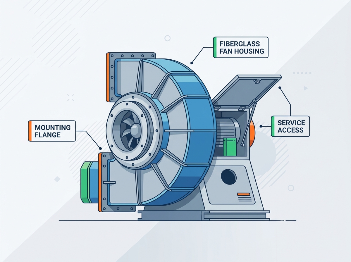
Clearance engineering balances aerodynamic efficiency with physical safety. It dictates how well the equipment performs and how safely technicians can interact with it during routine service. Poor clearance planning leads to turbulent airflow, reduced exhaust capacity, and dangerous maintenance conditions. Evaluating clearance dimensions requires looking at both the internal mechanics of the fan assembly and the external physical constraints of the installation site.
Internal clearance dictates the aerodynamic efficiency of the entire ventilation system. You must define acceptable tolerances between the impeller blade tips and the interior wall of the enclosure. If the gap is too large, air slips back over the blade tips, causing aerodynamic stalling, increased noise, and massive efficiency losses. If the gap is too tight, the risk of physical contact increases dramatically, which can shatter composite blades or spark metal impellers.
Engineers must account for multiple variables when setting this tolerance. Thermal expansion is a primary factor. Composite materials and metal impellers expand at different rates when exposed to hot exhaust gases. Operational deflection also plays a role; heavy blades bend slightly forward under aerodynamic load. Finally, you must account for bearing wear over time. As bearings age, the impeller shaft exhibits slight radial play. The internal clearance must accommodate all these factors simultaneously to prevent catastrophic blade strikes against the composite wall.
Fan Diameter (Inches) | Minimum Tip Clearance (Inches) | Maximum Tip Clearance (Inches) | Primary Expansion Concern |
|---|---|---|---|
12" - 24" | 0.125 | 0.250 | Bearing radial play |
25" - 48" | 0.187 | 0.375 | Aerodynamic blade deflection |
49" - 72" | 0.250 | 0.500 | Thermal expansion differentials |
External clearance ensures the system can be installed, operated, and maintained safely. Establishing minimum clearance distances from the housing to ceilings, walls, and adjacent structural supports is mandatory. For large industrial units, maintaining specific 4-to-8-foot ceiling clearances is often required, depending on the fan diameter and airfoil design. This space prevents restricted airflow on the intake side, which starves the fan and reduces exhaust volume.
Electrical service routing requires dedicated, unobstructed space. Technicians need room around the housing for safe electrical conduit installation, motor wiring, and future electrical diagnostics. Forcing conduits into tight spaces creates safety hazards and violates electrical codes. Additionally, preventing system effect is critical. You must guarantee adequate space on both the intake and exhaust sides. Poor inlet conditions, such as elbows, dampers, or transitions placed too close to the fan, create turbulent aerodynamic drag. This turbulence drastically reduces fan performance and increases vibration.
Maintain a minimum 4-foot clearance from the intake bell to the nearest solid wall or obstruction.
Ensure 36 inches of unobstructed space around the motor disconnect switch for OSHA compliance.
Keep exhaust discharge paths clear of structural overhangs to prevent corrosive gas accumulation.
Route all flexible conduits away from access doors, inspection ports, and removable duct sections.
Verify the ceiling height accommodates overhead lifting hoists for safe motor and impeller removal.
Upfront engineering for accessibility drastically reduces long-term operational expenditures. Maintenance in harsh environments is inherently difficult. If equipment is hard to reach, routine service gets delayed or ignored entirely, leading to premature failure. Designing enclosures with serviceability in mind transforms multi-hour, labor-intensive teardowns into rapid, predictable service intervals. This approach minimizes facility downtime and keeps maintenance personnel safe from unnecessary exposure to hazardous environments.
Inline axial fans present unique maintenance challenges. Because they sit directly within the ductwork, accessing the internal impeller often requires dismantling large sections of the ventilation system. Specifying flanged, removable sections of ductwork on either side of the axial fan solves this problem. These sections, often called spool pieces, allow for easy removal, deep cleaning, and impeller inspection without dismantling the primary enclosure or disturbing the main structural mounts.
When designing these access points, engineers must evaluate flexible connectors versus rigid fiberglass spool pieces. Flexible connectors absorb vibration and make removal easy, but they degrade faster in highly corrosive airstreams. Rigid fiberglass spool pieces maintain the chemical resistance of the entire system but require highly precise flange alignment during installation. The choice depends on the specific chemical makeup of the exhaust air and the frequency of required internal inspections. Regardless of the choice, you must specify chemical-resistant gaskets, such as PTFE or Viton, to seal these removable sections.
Direct internal access is non-negotiable for industrial exhaust systems. Designing sealed, bolted, or quick-release access panels directly into the composite enclosure allows technicians to inspect blades, clean chemical residue, and check internal clearances quickly. These doors must be strategically placed to provide a clear line of sight to the most critical internal components, specifically the impeller hub and the internal bearing assemblies.
Crucially, these access ports must maintain the same pressure rating and corrosion resistance as the primary housing body. A poorly designed access door becomes a weak point for chemical leaks and pressure loss. Gaskets must be specified using chemical-resistant elastomers depending on the exhaust composition. The hardware securing the doors must be 316 stainless steel, and the door panels themselves should be reinforced with structural ribs to prevent bowing outward under high positive static pressure.
External components require just as much protection as the internal airstream. Motors, belts, drives, and bearings mounted on the exterior of the fan housing are exposed to ambient facility conditions. Protecting these external drive components and personnel without restricting necessary airflow or compromising the structural integrity of the main enclosure requires specialized accessories engineered for the specific environment.
Exterior-mounted motors and belt drives need shielding from weather, washdown chemicals, and airborne debris. Specifying ventilated fiberglass covers provides this necessary protection. These covers must be engineered to withstand the same corrosive environment as the main fan body. They shield sensitive electrical components from direct water spray during high-pressure facility washdowns and prevent chemical dust accumulation on the motor's cooling fins.
However, you must balance the need for weather and washdown protection with the requirement for adequate motor cooling. Totally enclosed covers trap heat, leading to premature motor failure and bearing degradation. Ventilated covers utilize louvered designs or baffled intake slots to allow ambient air to circulate over the motor while keeping bulk water out. Additionally, integrating discharge cones and aerodynamic accessories at the exhaust point improves overall exhaust efficiency while maintaining the structural integrity of the entire assembly.
Personnel safety around rotating equipment is strictly regulated. OSHA-compliant fan guards are mandatory for any exposed moving parts, including belts, pulleys, and cooling fans. Installing these guards requires careful machine preparation and precise fan guard positioning prior to hardware installation. This ensures perfect alignment and prevents the guard from rubbing against the rotating shaft or belts, which creates friction and fire hazards.
Engineers should integrate structural mounting points directly onto the composite housing during the manufacturing process. Drilling into the housing after the fact compromises the fiberglass matrix, exposes raw glass fibers to chemicals, and creates pathways for corrosive gases to escape. These factory-integrated mounting points allow for the secure attachment of metallic or composite safety guards. It is vital to ensure that guard installation does not interfere with the primary mounting flanges, structural supports, or routine maintenance access paths.
Even the most perfectly engineered composite enclosure can fail if installed incorrectly. The transition from design to physical installation introduces numerous variables. Addressing common points of failure during the installation and commissioning phases ensures the equipment performs as intended. Site preparation, structural verification, and rigorous commissioning protocols are the final steps in securing system reliability.
Before moving the equipment into place, contractors must verify that the existing building infrastructure or mounting skids can support the dynamic load. A composite enclosure is lighter than steel, but the combined weight of the fan, motor, and ductwork remains substantial. Structural engineers must sign off on the load-bearing capacity of the I-beams or concrete pads to prevent long-term sagging.
Confirming electrical service capacity and routing paths prior to physically mounting the unit prevents last-minute installation conflicts. Conduits must be routed to avoid blocking access doors or removable spool pieces. Furthermore, mitigating uneven mounting surfaces is critical. If a composite flange is bolted to a warped or uneven steel beam, it induces severe twisting and torsional stress on the fiberglass. Installers must use stainless steel shims or self-leveling epoxy grouts to create a perfectly flat mounting surface before tightening any bolts.
Commissioning a composite fan system requires strict adherence to manufacturer guidelines. Securing and reviewing the manufacturer's specific installation, operation, and maintenance manuals for composite fan technology is the first step. These manuals contain the exact torque specifications, clearance tolerances, and operational limits for the specific unit.
Pre-startup verification must include checking all torque values on mounting hardware. Installers must ensure bolts are tight enough to secure the unit but not so tight that they crush the flanges. Finally, manual rotation checks are mandatory. Technicians must physically spin the impeller by hand to verify internal clearances before energizing the system. This simple check ensures no tools were left inside, no housing distortion occurred during mounting, and the blades clear the composite walls smoothly without scraping.
Consult with a ventilation engineer to review site-specific dynamic loads and structural capacities before finalizing the equipment schedule.
Request detailed CAD models from the manufacturer to verify external clearances and electrical routing paths against existing facility infrastructure.
Establish a standardized maintenance access protocol, including designated spool piece removal paths, prior to procurement.
Specify 316 stainless steel hardware and appropriate elastomeric vibration isolators for all structural mounting points.
A: Internal clearance varies based on fan diameter and operating temperature. Typically, it ranges from 0.125 to 0.25 inches between the blade tip and the housing wall. This tolerance accommodates thermal expansion, bearing wear, and aerodynamic deflection to prevent blade strikes while maintaining optimal exhaust efficiency.
A: This manufacturing method uses high pressure and matched metal dies to cure the fiberglass. It yields a higher glass-to-resin ratio and eliminates air voids. The process creates highly uniform, dense flanges with precise dimensional tolerances, making them significantly more resistant to cracking and crushing under torque.
A: Yes, protective covers can often be retrofitted. You must ensure the existing housing has adequate structural integrity to support the additional weight. Modifications should utilize factory-approved mounting techniques to avoid drilling unsealed holes into the primary composite matrix, which compromises chemical resistance.
A: Always use marine-grade or 316 stainless steel hardware to match the corrosion resistance of the enclosure. Installations require heavy-duty stainless steel backing washers to distribute clamping force evenly. You must also use calibrated torque wrenches to prevent over-tightening and crushing the composite flange material.
A: Ensure proper access by specifying removable flanged duct sections or rigid spool pieces on either side of the fan. Additionally, integrate sealed, bolted access doors directly into the housing. This allows technicians to inspect impellers and clean internal components without dismantling the entire ventilation system.
A: Industrial fans generate continuous high-frequency vibrations. If transmitted directly into rigid composite flanges, this kinetic energy causes micro-fractures in the resin matrix. Over time, these fractures lead to catastrophic structural failure. Neoprene pads or spring isolators absorb this vibration, protecting the integrity of the fiberglass.
