


Views: 0 Author: Site Editor Publish Time: 2026-11-02 Origin: Site


The most common point of failure in composite assemblies rarely involves the fiberglass matrix itself. Instead, joints where dissimilar materials meet take the brunt of the stress. Engineers specifying hardware attachment methods face a strict trade-off between upfront tooling complexity, production cycle times, and ultimate mechanical reliability. Choosing the wrong attachment method leads to joint failure under dynamic loads or bloated manufacturing workflows. Evaluating whether to integrate fasteners directly during the molding process or attach them post-cure requires rigorous analysis. You must assess load requirements, production volumes, and the specific manufacturing realities of the chosen composite process. We will evaluate the mechanics, advantages, and limitations of molded-in inserts versus bonded mounting hardware to help you optimize structural integrity and production efficiency.
Mechanical Superiority vs. Production Speed: Molded-in inserts offer superior resistance to torque and pull-out forces by mechanically locking into the cured resin, but they increase cycle times and tooling complexity.
Flexibility and Cost Efficiency: Bonded hardware reduces upfront mold costs and allows for late-stage design changes, making it highly effective for lower-volume runs or complex geometries where molding inserts is geometrically impossible.
Quality Assurance Dependency: Bonded joints rely heavily on strict surface preparation protocols, whereas molded-in inserts shift the quality burden to precise mold design and resin flow management.
Volume Thresholds Dictate Strategy: High-volume production generally favors the unit-cost efficiency of molded-in inserts, while prototyping and low-volume manufacturing lean toward secondary bonding.
Composite joints must meet strict baseline requirements to ensure long-term structural integrity. You must define the required pull-out strength, shear resistance, and torque-out limits before selecting a fastening method. Environmental exposure tolerances also play a major role. Fasteners face thermal cycling, moisture ingress, and potential chemical exposure on the job site. A successful joint transfers loads efficiently between the composite matrix and the attached component without inducing localized stress concentrations. Engineers must evaluate these load vectors carefully. They must account for dynamic vibrations from heavy machinery, static weight from mounted equipment, and potential impact forces during operation.
These requirements shift drastically based on the end-use application. Structural aerospace components demand zero-tolerance failure margins and exceptional fatigue resistance. In contrast, industrial applications like custom fiberglass covers prioritize environmental sealing, configuration flexibility, and impact resistance. Protective enclosures often require hardware that can withstand repeated opening and closing cycles by maintenance crews. The attachment method must align with the specific operational demands of the final product. Over-engineering a simple enclosure wastes resources and extends lead times. Under-engineering a structural joint invites catastrophic failure in the field.
Resin Transfer Molding introduces specific variables into hardware integration. The RTM process utilizes closed molds, injecting catalyzed resin under pressure into a dry fiber preform. This closed-mold environment creates distinct challenges for hardware integration. Engineers must account for blind inserts, potential resin flow disruption, and internal pressure variations. RTM injection pressures can easily exceed 30 psi. If an insert isn't pinned securely, that pressure will dislodge it, resulting in a scrapped part and a fouled mold. Furthermore, the hardware itself can alter the resin flow path, creating dry spots or resin-rich zones that weaken the laminate. Successfully integrating fasteners into RTM fiberglass parts requires precise mold design and careful preform manipulation on the shop floor.
Molded-in inserts integrate directly into the composite part during the primary manufacturing phase. Operators place knurled, undercut, or hex-shaped inserts into the mold cavity prior to resin injection. The dry fiberglass reinforcement is often tailored or cut to fit snugly around these inserts. Once the mold closes, the injected resin flows around the hardware. As the resin cures, it mechanically encapsulates the insert. The knurling and undercuts provide physical locking mechanisms. This prevents the insert from rotating or pulling out of the cured matrix when subjected to heavy loads.
This approach offers significant mechanical advantages. It ensures continuous fiber load transfer across the joint. The mechanical encapsulation provides superior resistance to vibration and dynamic loading, which is essential for engine mounts or suspension components. Molded-in inserts eliminate secondary assembly steps, streamlining the post-cure workflow. The joint achieves its maximum strength immediately upon demolding. You do not need to wait for secondary adhesives to cure or worry about clamping fixtures. This method excels in applications requiring high torque-out resistance, such as threaded mounting points for heavy machinery panels.
Implementing molded-in inserts requires strict adherence to Design for Manufacturability guidelines. You must establish minimum edge distances to prevent breakout failures under load. Boss wall thicknesses must be carefully calculated to avoid resin-rich zones. Resin-rich areas lack fiber reinforcement. They act as unreinforced plastic, becoming brittle and serving as primary crack initiation points under stress. Engineers must manage the localized fiber volume fraction around the insert. Cutting too many fibers to accommodate the hardware weakens the surrounding structure. Proper DFM ensures the insert enhances rather than compromises the part's structural integrity.
Design Parameter | Recommended Guideline | Field Application Note |
|---|---|---|
Minimum Edge Distance | 2.0 x Insert Diameter | Prevents side-wall blowout during high-torque bolt tightening. |
Boss Wall Thickness | 1.5 x Insert Diameter | Maintains structural rigidity without creating excessive resin pooling. |
Insert Knurling Type | Diamond or Hexagonal | Provides maximum resistance against both pull-out and rotational torque. |
Fiber Orientation | Continuous around insert | Avoid cutting primary load-bearing fibers; part fibers around the boss. |
Despite their mechanical superiority, molded-in inserts introduce distinct production trade-offs. They significantly increase tooling complexity. The mold requires precision-machined pins, magnets, or specific recesses to hold the inserts securely against injection pressure. There is a constant risk of resin flash entering internal threads during the pressurized RTM process. Manufacturers often use silicone plugs or blind inserts to mitigate this risk, adding another step for the operator. Additionally, molded-in inserts result in longer cycle times. Operators must manually place and secure each insert before every single shot, reducing overall daily throughput on the production line.
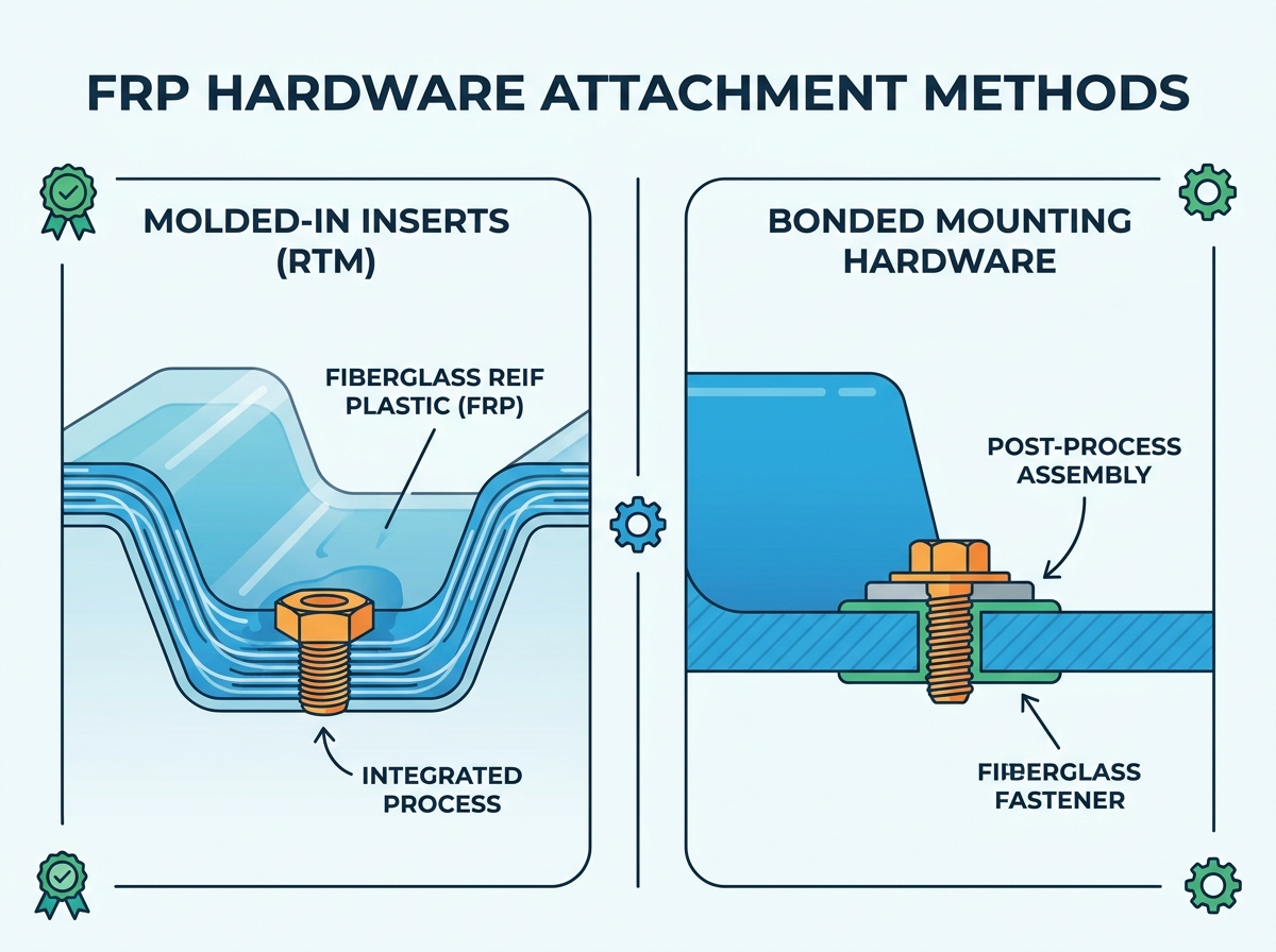
Secondary bonding utilizes structural adhesives to attach baseplates, studs, or standoffs after the composite part has fully cured. This technique separates the primary molding process from the hardware integration phase. Operators demold the part, prepare the surface, apply the adhesive, and position the hardware using specialized jigs. The adhesive forms a chemical and mechanical bond between the hardware baseplate and the composite substrate. This method relies entirely on the strength of the adhesive layer and the quality of the surface preparation executed by the shop floor technicians.
Selecting the correct adhesive is paramount for bonded hardware success. The adhesive matrix must match the specific load and environmental requirements of the installation site.
Adhesive Category | Primary Strengths | Best Field Applications |
|---|---|---|
Toughened Epoxies | Highest ultimate strength, excellent structural rigidity, high shear capacity. | Static load bearing, heavy equipment mounting, structural brackets. |
Methyl Methacrylates (MMAs) | Excellent fatigue resistance, tolerates minimal surface prep, fast room-temperature cure. | Marine environments, high-vibration panels, rapid assembly lines. |
Polyurethanes | High flexibility, superior vibration dampening, accommodates thermal expansion. | Impact-prone areas, joining dissimilar materials with high CTE mismatch. |
Bonded hardware offers immense flexibility and tooling benefits. It has zero impact on primary mold design. You do not need complex pins, threaded rods, or magnets in the tooling. This drastically reduces upfront mold manufacturing time and machining costs. It also allows you to standardize a single molded part for multiple configurations. You simply vary the bonded hardware placement based on the specific customer order or field requirement. This approach accelerates primary molding cycle times. Operators can inject parts continuously without stopping to load inserts, maximizing the output of the RTM press.
However, bonded systems possess specific vulnerabilities. They are highly susceptible to peel stress. Adhesives perform exceptionally well in shear and compression, but peel forces easily initiate delamination at the bond line. Bonded joints can degrade under extreme thermal cycling or harsh chemical exposure over years of service. Furthermore, this method relies absolutely on operator consistency. Poor surface preparation guarantees joint failure.
To ensure a reliable bond, operators must follow a strict surface preparation sequence:
Solvent Wipe: Remove heavy surface contaminants, oils, and loose debris using an approved solvent like isopropyl alcohol or acetone.
Mechanical Abrasion: Scuff the bonding area using 80-grit sandpaper or a controlled grit-blasting system to remove the glossy resin-rich surface layer.
Dust Removal: Vacuum or blow off the abraded dust using clean, oil-free compressed air.
Final Solvent Wipe: Perform a secondary wipe to ensure a completely pristine bonding surface.
Adhesive Application: Dispense the adhesive using a static mixing nozzle to guarantee the correct resin-to-hardener ratio.
Comparing these two methods requires a multi-dimensional evaluation. Engineers must weigh mechanical performance against production economics and quality control requirements. The optimal choice depends entirely on the specific constraints of your manufacturing environment and the end-use application.
Molded-in inserts generally provide superior ultimate tensile strength and torque resistance. The mechanical interlocking with the cured resin matrix distributes loads effectively across the fiber network. When a molded-in insert fails, it typically results in matrix failure. The surrounding fiberglass actually fractures before the insert pulls free. Bonded hardware relies on the adhesive's shear strength. While modern structural adhesives are incredibly strong, they remain vulnerable to peel forces. Bonded joint failures typically manifest as adhesive failure, where the glue separates from the substrate, or cohesive failure, where the adhesive itself tears under load.
Production volume dictates the economic viability of each method. Molded-in inserts require expensive, complex tooling. However, they eliminate secondary assembly labor. High-volume production runs quickly offset the initial tooling investment through reduced labor hours per unit. Bonded hardware features minimal tooling investment. Yet, it requires significant manual labor for surface preparation, adhesive application, and fixturing. The break-even point occurs when the labor savings of eliminating secondary bonding surpass the high upfront tooling costs of molded-in inserts. Low-volume runs, custom orders, and prototypes heavily favor bonded hardware due to the low barrier to entry.
Inspection requirements differ drastically between the two methods. Molded-in inserts require dimensional and visual checks. Inspectors verify insert presence, correct thread pitch, and the absence of resin flash inside the threads. Bonded joints present significant non-destructive testing challenges. Visual inspection cannot confirm the internal integrity of an adhesive bond. You cannot easily detect voids or poor substrate wetting once the hardware is attached. Therefore, rigorous FRP quality control protocols must focus heavily on process validation for bonded joints. You must audit surface preparation steps, monitor shop floor humidity, and verify adhesive mix ratios continuously.
Validating joint integrity requires standardized testing. Engineers utilize specific ASTM standards to audit performance against baseline requirements. For molded-in inserts, ASTM D5961 measures the bearing response of polymer matrix composite laminates. This helps determine how the composite handles loads transferred through the insert. For bonded hardware, ASTM D1002 evaluates the apparent shear strength of single-lap-joint adhesively bonded metal specimens. Conducting these standardized tests ensures your chosen fastening method meets regulatory and safety compliance standards for your specific industry.
Feature | Molded-In Inserts | Bonded Mounting Hardware |
|---|---|---|
Primary Load Strength | Excellent (Tension, Shear, Torque) | High (Shear, Compression), Poor (Peel) |
Tooling Complexity | High (Requires pins, magnets, recesses) | Low (No primary mold modifications) |
Production Cycle Time | Slower (Manual loading before injection) | Faster primary molding, slower post-assembly |
Design Flexibility | Rigid (Changes require mold modification) | High (Hardware placement easily adjusted) |
Quality Assurance Focus | Mold design, resin flow, flash prevention | Surface preparation, adhesive mixing, curing |
Both fastening methods carry inherent implementation risks. Anticipating these risks and deploying targeted mitigation strategies ensures long-term joint reliability. Engineering oversight must extend beyond the initial design phase into active production monitoring on the shop floor.
Differences in the Coefficient of Thermal Expansion between metal inserts and the fiberglass matrix create significant stress. As temperatures fluctuate in outdoor environments, the metal expands and contracts at a different rate than the composite. This mismatch causes micro-cracking in the surrounding resin, eventually leading to joint failure. To mitigate this risk, select appropriate insert materials. Brass and specific stainless steel alloys offer CTE profiles that align closer to certain composite matrices. Additionally, utilizing localized reinforcement, such as extra glass plies around the insert boss, helps distribute thermal stresses more evenly across the laminate.
Galvanic corrosion occurs when dissimilar metals interact in the presence of an electrolyte. While this is a severe problem in carbon-fiber reinforced plastics, it remains a factor in standard fiberglass applications exposed to harsh environments like saltwater or chemical washdowns. If a steel bolt threads into a brass insert, corrosion can seize the joint or degrade the hardware. Mitigate this risk by using isolated standoffs. You can also specify coated inserts or apply specific adhesive barriers to prevent direct metal-to-metal contact within the joint assembly.
Adhesive failure remains the primary risk for bonded hardware. Contamination from mold release agents prevents proper adhesive wet-out. Even microscopic layers of silicone or wax will destroy bond integrity. Implement strict peel-ply usage during molding. Peel-ply leaves a textured, clean surface upon removal, ideal for bonding without extensive sanding. Standardize your abrasion techniques using specific grit sandpaper or automated grit blasting. Finally, utilize automated adhesive dispensing systems to ensure perfectly accurate mix ratios and minimize human error during application.
Joints can degrade unnoticed over the product's lifespan. Dynamic vibrations, UV exposure, and chemical ingress weaken both molded-in and bonded connections over time. Establish strict protocols for routine field inspection. Maintenance teams should check for micro-cracking around molded-in inserts during scheduled downtime. For bonded joints in harsh environments, inspectors must look for early-stage delamination or adhesive chalking. Implementing a proactive lifecycle auditing program detects minor degradation before it escalates into catastrophic mechanical failure in the field.
Conduct finite element analysis on the proposed joint to identify localized stress concentrations before finalizing the mold design.
Request physical pull-test and shear-test data from your composite manufacturing partner to validate the chosen adhesive or insert under real-world loads.
Prototype both attachment methods using a temporary mold if your anticipated production run exceeds 1,000 units annually.
Standardize your surface preparation protocols and document the exact grit, solvent, and cure times in your shop floor quality control manual.
A: Molded-in inserts provide higher pull-out strength. They mechanically lock into the cured resin matrix. The knurling and undercuts distribute tension loads across the composite structure. Bonded hardware is limited by the shear and peel strength of the adhesive layer, making it more vulnerable to direct pull-out forces.
A: Yes, provided the joint is designed correctly. The design must keep the adhesive in shear or compression rather than peel or tension. You must use high-performance structural adhesives, such as toughened epoxies or MMAs, alongside strictly enforced surface preparation protocols to ensure structural integrity.
A: Molded-in inserts increase initial tooling costs significantly. The mold requires precision-machined pins, magnets, or recesses. These features must hold the inserts securely against the high injection pressure of the RTM process, requiring tighter machining tolerances and more complex mold engineering.
A: Manufacturers typically use blind inserts, which are closed at one end. Alternatively, they use silicone masking plugs. Specialized mold designs can also create a tight mechanical seal against the face of the insert, preventing pressurized resin flash from entering the internal threads during injection.
A: Switching from molded-in to bonded is relatively easy. It usually only requires removing the holding pins from the existing mold. However, switching from bonded to molded-in is difficult and expensive. It often requires the mold to be heavily modified or entirely remade to accommodate the new insert holding mechanisms.
A: It is absolutely critical. Any residual mold release agent, dust, or moisture on the part surface will cause catastrophic adhesive failure. Strict quality control protocols for surface abrasion, solvent wiping, and adhesive mix verification are mandatory to ensure repeatable, reliable bonded joints.
A: Methyl Methacrylates (MMAs) are often preferred. They offer excellent fatigue resistance and fast cure times. Most importantly, they possess the ability to bond effectively with slightly less rigorous surface preparation compared to traditional epoxies, biting through minor surface contaminants effectively.
